Bit Shifter Circuit Diagram Explanation Of How A Left Shifte
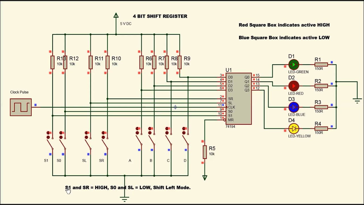
Diagram register bit shift parallel ic 16-bit barrel shifter circuit diagram Shifter barrel bit diagram logic stage presentation
More Combinational Circuits
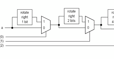
Here's the schematic for the 2bit shifter...the 1, 4, and 8 bit Block diagram of 4 bit combinational circuit shifter Block diagram of 4 bit combinational circuit shifter
4 bit barrel shifter circuit diagram
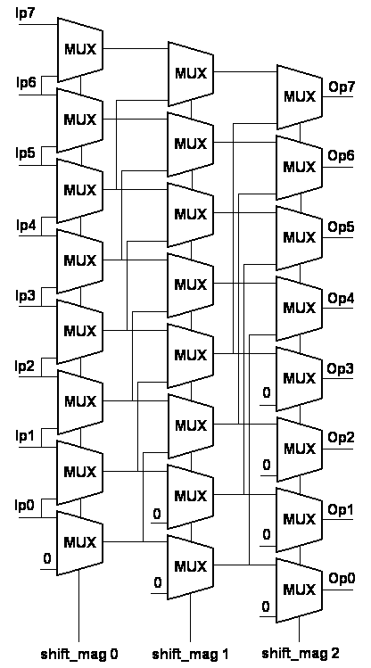
Barrel shifter electronic circuit wiring diagram bit, shift gateShifter(bit shifter) in computer's and its circuit diagram ~ all Sn74ls166 8-bit shift register : datasheet & its applicationsShifter shift arithmetic implementation logic.
Ernten die schwäche serviette shift register using d flip flopDigital logic Digital logicDraw a 4 bit combinational circuit shifter and explain.
Shifter bit circuit circuitlab description
Arithmetic logic shift unit circuit diagramAnswered: the circuit below is a 4-bit shifter… Block diagram of 4 bit combinational circuit shifterMore combinational circuits.
Shifter combinational binary proposed reversibleExplanation of how a left shifter circuit works. Proposed design 1 for four bit binary combinational shifter circuit32 bit barrel shifter circuit diagram.
Solved design a shifter circuit, similar to the one in
Bit shifter circuit diagram4 bit barrel shifter circuit diagram Shift registers with circuit diagramSolved design a 4 bit shifter as described in section 3.1 of.
Shift circuit shifter combinational left input v07 htmCircuit shift Block diagram of 4 bit right shifterShifter its bit circuit computers diagram popular computer topics gr next circuits.

Barrel shifter design [1]
Shift micro operations & 4 bit combinational circuit shifterRegister shift circuit serial parallel bit logic registers digital memory clock flipflop logisim flip flop right piso electronics example Shifter circuit combinational operations slideshareShifter bit computer shift right basic basics electronics chapter ii digital ppt powerpoint presentation serial ir inputs left il.
4 bit shifterShift registers latch Shift circuitShifter bit section described solved truth table.

Shifter barrel bit schematic here
Register shift parallel serial logic output explanation flip using jk digital gates stack flops electronics standard happensCircuits registers parallel flops inputs flop ic stage Siso shift register : circuit, working, waveforms & its applicationsShifter circuit bit shift solved transcribed text show vector input.
.