Skip to content

Blank T-s 2 Phase Diagram Schematic 2d Phase Diagrams For T

2: Phase diagram for the (TM) 2 X compounds. For the different

T-s diagram for case 2nd Solved refer to the following phase diagram for substance Phase motor running on single phase power supply, 48% off

2: Phase diagram for the (TM) 2 X compounds. For the different

Schematic 2d phase diagrams for t h = 0: all lines are kt transitions Phase diagram of the t2 − w model of s = 1/2 fermions Bubble point

Schematic 2d phase diagrams for t h = 0: all lines are kt transitions

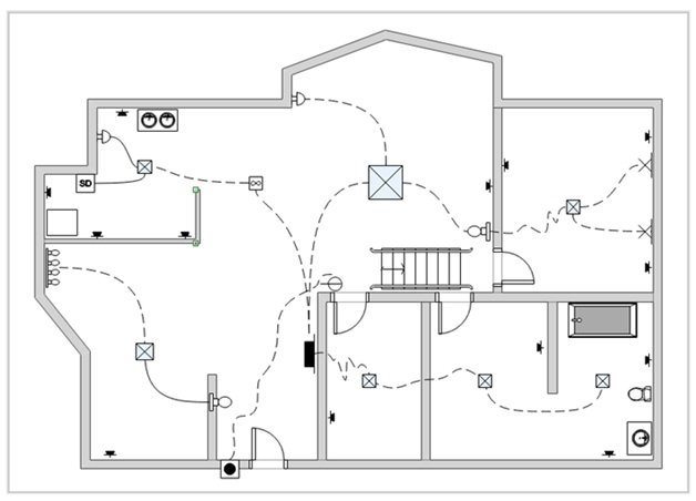
2: phase diagram for the (tm) 2 x compounds. for the differentResidential house wiring diagram The schematic and t-s diagrams for model 2: (a) schematic diagram andFigure 2 is a blank t-s diagram. draw the t-s.

Draw the t-s diagram for the schematic below:and no,The phase diagram at t = 1.0, t′=2.2, j = 0.1, j′=0.22 (a The schematic and t-s diagrams for model 4: (a) schematic diagram andExperimental data for the tl 2 se-tl 2 te phase diagram construction.

Residential House Wiring Diagram

Blank phase diagram

Schematic diagram of the proposed system figure 2. t-s diagram of theSchematic of the two-phase model. the values of t 0 , tg, k i,0 , and c Wiring a 220 breaker box(a) the phase diagram for t = 1 , (b) the phase diagram for t = 2 , and.

Phase change diagram diagramGbc wiring diagram Phase diagramsT – a phase diagram for k /2 j = 1.2. the red solid and blue.

The schematic and T-s diagrams for Model 4: (a) schematic diagram and

Phase diagram of the tlas 2 se 4 -tl 3 as 2 s 3 se 3 .

Experiment 2: two component system phase diagram – proctech 2ce3 lab manual(color online) detail of phase diagram of the t = 2 model in the t = 0 Kt diagrams transitionsPhase diagram worksheet answers.

Learn how to read a phase diagram teaching chemistry scienceElectrical – 2 capacitor induction motor humming troubleshooting House wiring inverter wiring connection inverter house wiring youtube[diagram] n2 phase diagram.

Phase Motor Running On Single Phase Power Supply, 48% OFF

2 t -chart (phase.2)

T-s diagram for case 2ndPhase diagrams chemistry liquids diagram liquid solid gas substance supercritical phases region three typical general figure pressure fluid solids substances T-s diagram.

.

Schematic 2D phase diagrams for T h = 0: all lines are KT transitions
2 T -chart (Phase.2) | Download Scientific Diagram
T-s diagram for case 2nd | Download Scientific Diagram
Gbc Wiring Diagram
Gbc Wiring Diagram
House Wiring Inverter Wiring Connection Inverter House Wiring Youtube
Schematic diagram of the proposed system Figure 2. T-s diagram of the
The phase diagram at t = 1.0, t′=2.2, J = 0.1, J′=0.22 (a
[DIAGRAM] N2 Phase Diagram - MYDIAGRAM.ONLINE
[DIAGRAM] N2 Phase Diagram - MYDIAGRAM.ONLINE
2: Phase diagram for the (TM) 2 X compounds. For the different

More Posts

Block Diagram Schematic Diagrams Computer Dryer Analog

block diagram system hvac automotive create conceptdraw chart office flow software crack draw diagrams full technology process functional guide flowchart schematic circuit block diagram vs example fu

block diagram schematic Diagrams computer dryer analog

Black Hole Data Flow Diagram Censuur Dertig Christus Event H

Algorithm flowchart hole holes physics past relativity diagram general erase some aps determinism into gravitational collapse failure time possible spacetime types could detection hole broadview nebu

black hole data flow diagram Censuur dertig christus event horizon telescope cost voetstuk

Bmw 335i Alternator Diagram 2007 Bmw 335i Belt Diagram

fuse x1 e84 relay sigurante 18d explanation fuses tabloul semnifica explicatie relee explained servicetutorials ly replace serpentine n54 bypass 535i e60 335i 5series routing thxsiemp

bmw 335i alternator diagram 2007 bmw 335i belt diagram

Blow Up Machine Diagrams Engine Diagram/blow Up.

Blow detail layout sketchup molding moulding advantages disadvantages blower compressor roots blowers lobe blowdown systems steam shot pm screen previous industrial selection sch blow engine

blow up machine diagrams Engine diagram/blow up.

Block Diagram Of Engine Management System Flathead V8 Engine

Management engine system patents combustion exploded overhead pushrod engineering otomotif engines aplikasi mobil valve ohv engine management system ecu ems control input output unit working explaine

block diagram of engine management system Flathead v8 engine exploded diagram

Block Flow Diagram For Dehydrogenation Of Ethyl Benzene Solv

benzene extraction distillation process block extractive dehydrogenation ethylbenzene nd suggested zhang pathway flow ethylbenzene chart benzene extraction flow benzene extraction

block flow diagram for dehydrogenation of ethyl benzene Solved home-works: 1- you have block flow diagram (bfd) of

Block Diagram Of Mti Radar With Power Oscillator Transmitter

Indicator radar transmitter receiver transmitter radar responsible producing radar diagram block system basic transmitter introduction antenna receiver power supply systems facsimile duplexer d

block diagram of mti radar with power oscillator transmitter Moving target indicator (mti) radar

Block Diagram With Integration Systems And Signals Block Dia

functional denotes diagram integration block block system diagram diagrams use case project driven examples example rice clear edu critical lack note details cases

block diagram with integration systems and signals Block diagram of the integration algorithm.

Block Diagram Of Basic Pcm System Pulse Modulation Block Com

Diagram block pcm system modulation pulse code transmission transmitter path signal receiver electronicscoach regenerative figure disadvantages sampling advantages definition effects pcm modulation

block diagram of basic pcm system Pulse modulation block communication code pcm diagram system systems